How to Control Any Device with a Relay and Raspberry Pi

Updated May 13, 2024 06:12
Overview
This guide covers how to control electrical equipment like an appliance or battery-powered device with a Raspberry Pi. The Raspberry Pi operates at transistor-transistor logic (TTL) voltage levels (~3 volts) and doesn't have over-current protection on it's header pins so we need to use a relay to avoid damaging them. A relay circuit is a simple way to electrically isolate one system from another while still allowing them to connect. It's a great way to put solutions together where you want to programmatically activate and deactivate equipment that doesn't come with a digital interface (like USB or Bluetooth) to do so.
To set this up you will need:
- - A Raspberry Pi
- - Product you want to control
- - NPN mosfet transistor
- - 10kOhm resistor
- - Stuff to connect everything
Note: The last three items on the list can be bought together with any basic starter kit.
Note: To hack into electrical products you'll need some basic tools.
Designing the System
The Raspberry Pi runs a flavor of Linux called Raspberry Pi OS. It comes with low level drivers to control the hardware on the Raspberry Pi including it's 40 pin header. These drivers have bindings to all the programming languages that run on Linux like Python, Javascript, and Bash. This lets your applications switch the TTL voltages on the 40 pin header between HIGH (3V) and LOW (0V). Below is the software stackup illustrating how this is put together.
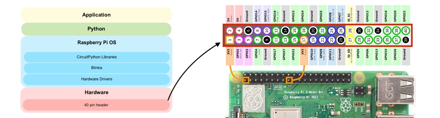
Familiarize yourself with the pin layout. We will focus on those labeled "GPIO" since this are for general purpose input/output control. These GPIOs aren't meant to drive large loads so trying to power external equipment directly can cause issues like brownouts or permanent damage to the RaspberryPi (like it bursting into flames). To avoid these issues we'll use a relay circuit spliced into the product we're trying to control.
Basic Relay Circuit
There's several types of relays to choose from but the most basic is a mosfet transistor that can support loads of 60V @ 32A, plenty for most products. Depending on the product, you can use it to control the product's power supply or in some cases it's internal buttons or momentary switches. Below are some sample circuits that are useful for controlling products.

On the left the mosfet is setup to control the product's overall power supply and is useful for simple equipment like lights, lock latches, heating elements and motors. On the right the mosfet is placed around a product button, allowing it to control when and for how long the button is pressed. This is great for product remotes or wireless car keys.
Note: The NPN mosfet requires a resistor R(GS) to prevent it from "sticking". A 10kOhm resistor should be enough for most applications but if you're experiencing lag in the switching time then try a smaller one.
Connect Circuit to Raspberry Pi
Now that we have a relay circuit, it's time to wire it up to the Raspberry Pi. As we covered above, there's plenty of GPIOs to choose from on the 40 pin header, 26 in total. For this exercise, we use a breadboard to connect everything up while keeping things neatly organized. We use a simple LED and separate power supply as our mock product, following the left setup discussed above. Here's how everything should look:
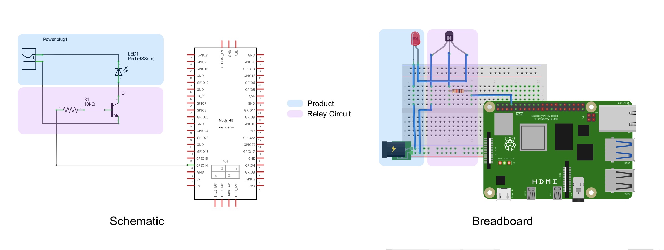
As you can see, we wired the control signal of the relay ciruit to GPIO14 on the Raspberry Pi header. But how do we control that pin state programmatically?? No worries, we'll tackle that next.
Scripting to Control Devices
To control our mock product, we'll need to setup some software on the Raspberry Pi. Python is a great option since it comes preinstalled on Raspberry Pi OS and it's a popular scripting language. To leverage a treasure chest of awesome interfaces and sample code, we'll need the CircuitPython libraries. CircuitPython is a lightweight version of Python (same syntax) that's designed for running scripts on microcontrollers that can't support Python proper. It's super handy for quickly building solutions but needs some wrapper code to talk to the Raspberry Pi's hardware drivers. For that we'll need the Blinka library from Adafruit. Follow these steps to get everything in place:
- Make sure you have the latest Raspberry Pi OS (Bullseye) and Python 3.7 (or later) installed.
- Install Blinka wrapper with the following commands (more details here):
sudo raspi-config nonint do_i2c 0
sudo raspi-config nonint do_spi 0
sudo raspi-config nonint do_serial_hw 0
sudo raspi-config nonint do_ssh 0
sudo raspi-config nonint do_camera 0
sudo raspi-config nonint disable_raspi_config_at_boot 0
sudo apt-get install -y i2c-tools libgpiod-dev python3-libgpiod
pip3 install --upgrade RPi.GPIO
pip3 install --upgrade adafruit-blinka
To check the installation worked, run this command:
ls /dev/i2c* /dev/spi*the output should look like this:
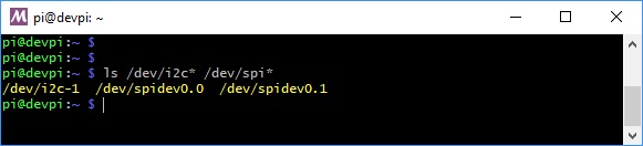 3. Download and unzip the latest CircuitPython Libraries. Add these folders to your Python path so that you can import the interfaces into your scripts (more details here). To check this worked, make sure this command doesn't return any errors:
python3 -c "import digitalio"Now that we have things setup, let's test it! Here's a sample python script you can try:
# need to include the libraries we'll use
import time
import board
import digitalio

# simple greeting to make sure we're running
print("hello ninja!\n")

# here we initialize GPIO14 and set it to OUTPUT
led = digitalio.DigitalInOut(board.D14)
led.direction = digitalio.Direction.OUTPUT
access = True

# here we loop if access is True
while access:
    led.value = True  # set LED to ON
    time.sleep(0.5)   # wait half a second
    led.value = False # set LED to OFF
    time.sleep(0.5)   # wait half a second
Verify the Product (aka the LED) is blinking. If not, check that the mosfet is wired to GPIO14, the resistor is installed correctly, and you have the power supply feeding at least 5V and grounded properly. Use a multimeter to verify connections and voltages.
Pass it in with PassNinja
Now that you can control stuff with a Raspberry Pi, it's really easy to manage access with PassNinja. Sign up now to create a pass with your access details and order a preconfigured VAS reader. Our VAS readers connect over USB and act as a keyboard so scanned passes send over their NFC message as typed input. Managing access to your product is now as simple as adding this line to the script above:
access = True if (input("Scan now:\n") == "your pass nfc message") else False # grab keyboard input and if correct, set to True, else FalseThis system may seem primitive but because of the widespread adoption of Apple and Google Wallets and their built in security measures, it's a great solution for self-service rental or loyalty reward stations. From lockers to electric scooters to parking gates, it's all game.
Conclusion
This guide went through setting up a Raspberry Pi to programmatically control stuff. We listed out all the hardware and software you need as well as put it all together into a working solution you can use. We're literally standing on the shoulders of giants, putting together the functionality for you to be a ninja and deploy amazing NFC experiences. If you post your builds on social media, make sure to tag us and we'll kick you some credits!
More articles focused on Hardware
This guide will cover the process of setting up a VAS reader to detect and verify Apple and Google passes over NFC. VAS readers are made by only a few manufacturers and mostly sold through third pa...
How To Read Apple Vas Passes Using An Acs Wallet MateIf you have an ACS WalletMate, you may be wondering how to use it to read Apple passes. In this article, we'll be going over the steps to do just that:
How To Read Nfc Data From Vtap Via IpadIn this guide, we'll show you how to create an iPad app that is capable of reading NFC data from Apple passes using a VTAP 100, SwiftUI, and some glue code. By the end of it, you'll have an app tha...
How To Configure A Socket Mobile S550 Bluetooth Nfc ReaderThis guide will cover the process of setting up a VAS compatible bluetooth enabled NFC reader to detect and verify Apple passes over NFC. VAS readers are made by only a few manufacturers and mostly...
How To Build An Nfc Car KeyThis guide will show you how to replace your car keys with an NFC-enabled pass in your Apple or Google Wallet. Not only will this free you from having to carry car keys but it allows you to grant (...